
VERTICAL SEPARATOR
Full separation performance. Half the floor space.
Where Space Is the Constraint -- and Performance Still Can't Be Compromised
Vertical separators are the specified solution wherever installation footprint drives the equipment selection. The physics of vertical separation also make them the preferred choice for gas-dominant streams and applications where liquid slugs are infrequent.

Tight Wellpad and Wellhead Installations
Multi-well pad development concentrates production equipment into a compact footprint. Horizontal separators require a long run of ground clearance; vertical units occupy a fraction of the surface area and can be mounted on a minimal concrete pad or integrated into a compact wellhead skid. For operators developing high-density well pads, vertical separators significantly reduce facility civil work and piping complexity.

Offshore Platform and FPSO Deck Space
On offshore platforms and FPSOs, deck space is one of the most expensive commodities. Equipment weight and projected footprint are primary selection criteria. Vertical separators deliver the required gas-liquid separation duty with a small deck footprint and favorable weight-to-capacity ratio -- making them the default choice for offshore first-stage separation where liquid loading is moderate.

Gas-Dominant Production Streams (High GOR)
When the gas-oil ratio is high, the liquid phase is a minority component. Vertical separators handle this flow regime naturally: the gas phase rises through the full vessel cross-section, while the small liquid volume accumulates at the bottom without flooding the separation zone. For wells with GOR above 500 Nm³/m³, vertical configuration is typically the more efficient design.

Skid-Mounted Modular Packages
Vertical separators are a core component of compact skid packages where all process equipment, valves, piping, and instrumentation must fit within a defined shipping envelope. The vertical orientation allows the skid designer to build around the vessel more efficiently -- running piping alongside the vessel body rather than end-to-end -- and reduces the overall skid length needed for transport.
Vertical Separation -- The Physics and the Engineering
In a vertical separator, the process fluid enters the vessel and separation occurs along the vertical axis. Understanding the physics of each zone explains why vertical configuration outperforms horizontal for specific operating conditions.
Inlet Zone -- Tangential or Baffle-Type Entry
Fluid enters the vessel through an inlet distributor positioned in the lower-to-mid section of the vessel. A tangential inlet induces a swirling flow pattern that uses centrifugal force to fling liquid droplets outward to the vessel wall, where they coalesce and drain downward. A baffle-type inlet redirects the incoming momentum and initiates primary gas-liquid disengagement by direct impaction. Inlet device selection depends on the GOR, velocity, and slug frequency of the incoming stream.
Gravity Separation Zone -- Countercurrent Flow
After the inlet zone, gas rises upward through the vessel while liquid falls downward. This countercurrent flow regime is the fundamental operating principle of vertical separation. The rising gas velocity must be below the terminal settling velocity of liquid droplets -- a function of vessel diameter and the droplet size distribution. LINSON OIL sizes vertical separator diameters using rigorous droplet settling calculations to ensure the design gas capacity is achieved at the specified operating pressure and temperature.
Liquid Accumulation Zone (Bottom)
Liquid collects in the lower section of the vessel, where a displacer or float-ball level controller maintains the liquid level within the operating range. The liquid hold-up volume in the bottom section provides surge capacity and ensures stable level control response. A vortex breaker on the liquid outlet nozzle prevents gas entrainment into the liquid discharge line.
Mist Extraction Zone (Top)
Gas exits through a wire mesh demister pad at the top of the vessel. The demister captures fine mist droplets -- typically in the 5-100 μm size range -- that pass through the gravity zone without settling. Clean gas exits the demister and the vessel through the gas outlet nozzle. For applications with very low carryover requirements, a vane pack or high-efficiency mesh pad is available.

Why Vertical Outperforms Horizontal for High-GOR Streams
In a horizontal separator, the gas phase travels along the vessel length horizontally, and liquid droplets must settle across the gas flow path. At high GOR, the large gas volume at high velocity makes it harder to keep liquid in the settling zone. In a vertical separator, the gas rises upward against falling droplets -- the geometry naturally filters out liquid. This makes vertical separators the lower-risk choice for gas-dominant applications.
Engineering Specifications
| Parameter | Standard Range | Notes |
|---|---|---|
| Orientation | Vertical | Standard for this product; horizontal available separately |
| Phase Separation | 2-phase or 3-phase | Internal configuration determines phase count |
| Design Pressure | 0.6 - 10.0 MPa (g) | Higher on request |
| Design Temperature | -20°C to +200°C | Material-dependent |
| Shell Material | Q345R / 16MnDR / 316L SS | Per fluid service and operating temp |
| Corrosion Allowance | 2 mm std / 3 mm sour | Up to 6 mm for aggressive environments |
| Inlet Device | Tangential / Baffle / Cyclone | Application-dependent; selected by LINSON OIL |
| Demister | Wire mesh, 5 μm standard | Vane pack or high-efficiency available |
| Level Control | Float-ball / Displacer | 4-20 mA DCS signal output |
| Design Life | ≥ 10 years | Per GB 150 design basis |
| Design Code | GB 150 / ASME VIII Div.1 | Dual certification for export |

Vertical Separator Sizing Reference (Indicative)
| Vessel ID | Approx. Gas Capacity at 1.0 MPa (Nm³/d) | Notes |
|---|---|---|
| DN400 | ~15,000 - 30,000 | Wellhead scrubber |
| DN600 | ~35,000 - 70,000 | Single/small multi-well |
| DN800 | ~65,000 - 130,000 | Multi-well gathering |
| DN1000 | ~100,000 - 200,000 | Station-scale |
| DN1200+ | Custom calculation | Consult LINSON OIL |
*Capacity figures are indicative at standard operating conditions. Actual sizing requires process data -- use the inquiry form below.
Standard Supply & Customization Scope
Standard Factory Configuration
- ▪ Inlet distributor (type selected per application)
- ▪ 5 μm wire mesh demister with support ring
- ▪ Float-ball liquid level controller with 4-20 mA output
- ▪ Vortex breaker on liquid outlet nozzle
- ▪ Pressure relief valve (spring-loaded, per code)
- ▪ Pressure gauge and transmitter connection nozzles
- ▪ Thermometer connection
- ▪ Inspection manhole (≥ DN400)
- ▪ Drain and vent connections
- ▪ Skirt or leg support structure & Lifting lugs
- ▪ Surface treatment: internal Sa2.5 blast + lining; external primer + topcoat
- ▪ Factory hydrostatic pressure test & Nameplate per GB 150
OEM / ODM Customization Options
- Three-phase internal configuration Oil/gas/water separation in vertical orientation; coalescer + dual level control
- Tangential inlet device High GOR, high-velocity inlet, severe slug suppression
- High-efficiency demister Vane pack or dual-stage for low carryover tolerance (fuel gas, instrument gas)
- Sour service package H₂S wet service; NACE MR0175 / ISO 15156 compliant materials and welds
- Full skid integration Vessel, valves, piping, instrumentation, structural steel -- factory pre-fabricated
- ASME U-stamp & 3.1 Certificates International / export project requirements (EN 10204)
Certified to Build It. Equipped to Test It. Ready to Prove It.
21 Years of Vertical Separator Supply

Sinopec & CNPC HSE Certified Supplier
Vertical separators and wellhead equipment are among the most frequently procured vessel types. LINSON OIL's qualification in both NOC systems reflects a delivery record spanning more than two decades.

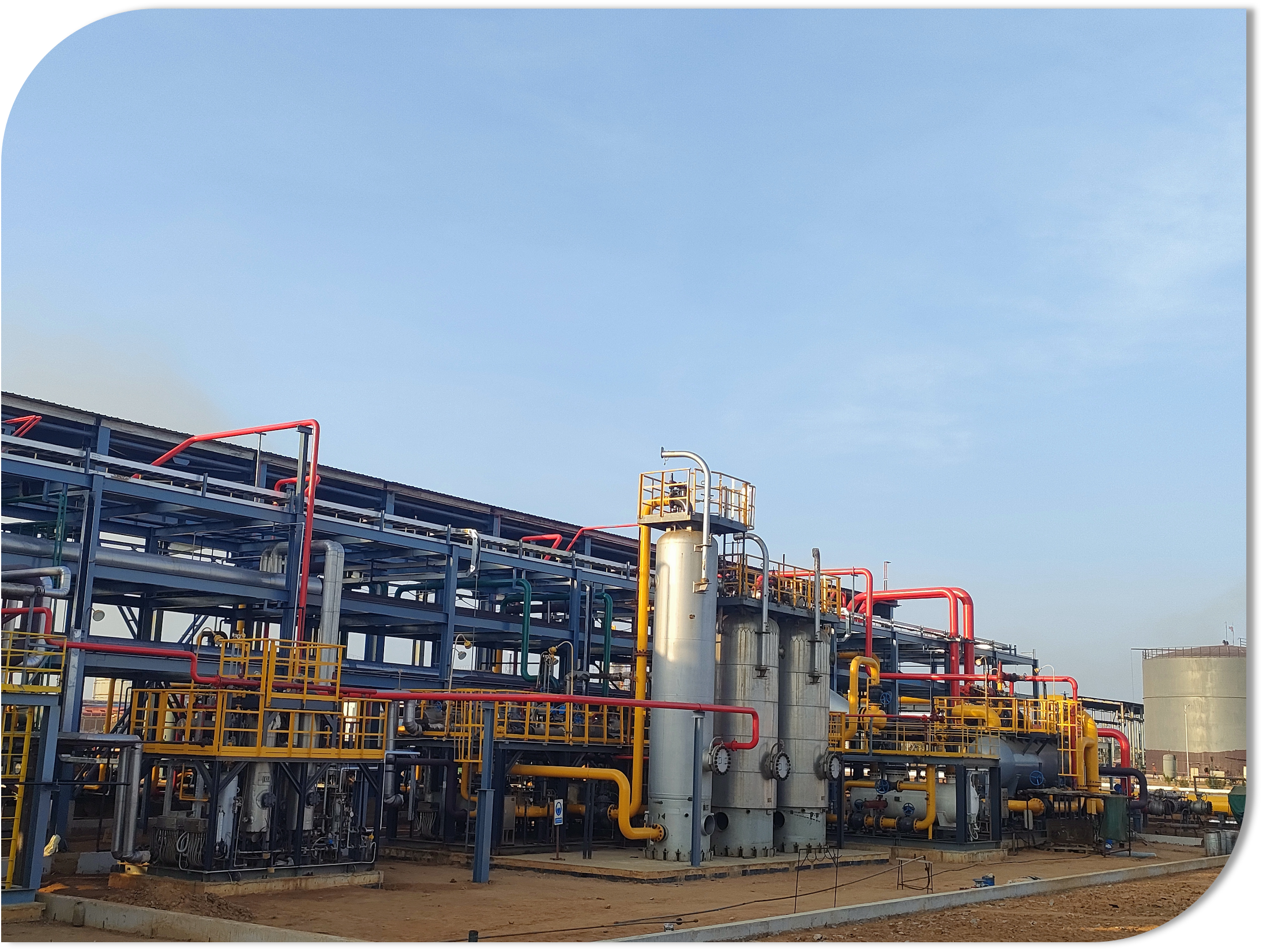
Skid-Mounted Packages
LINSON OIL has integrated vertical separators into skid-mounted wellhead and gathering station packages delivered to operators in Shandong, Xinjiang, and internationally. Pre-fabricated and tested at our 30,000 m² facility.
Congo (Brazzaville) Jiarou Oilfield
The associated gas recovery and LNG liquefaction system delivered included multiple separation vessel stages, demonstrating our capability to design and fabricate complex separation equipment for international projects.
Industry-Leading Warranty & Support
Standard: 2 years from commissioning or 26 months from shipment, whichever is earlier. The industry standard is 1 year. Our 2-year warranty is not a marketing tool -- it is built on 21 years of quality-controlled fabrication at a certified manufacturing facility.
Long-term partners: up to 2.5 years, including priority technical support and spare parts access.
After-Sales Support
- Remote process engineering consultation
- Spare parts documentation in quality dossier
- On-site commissioning support available
Space Is Tight.
Send us your process data and site constraints, and our engineering team will come back with a sized vertical separator recommendation -- including configuration rationale, indicative weight, and relevant project references.
No catalog selection. No automated response.
Submit your process parameters and receive:
- ✓ Preliminary vessel sizing (diameter, height, weight)
- ✓ Inlet device recommendation with technical rationale
- ✓ Configuration guide: vertical vs horizontal for your GOR
LINSON OIL -- 21+ Years | 5,000+ Projects | 87 Patents | Sinopec & CNPC HSE Certified Supplier