Gas-Liquid / Oil-Gas Separators
When inlet flow fluctuates -- slugs, surges, pulsations -- buffer separation keeps your process stable and your downstream equipment protected.
Designed for the Conditions That Standard Separators Struggle With
Steady-state flow is the assumption in textbook separator design. Real wellhead and gathering station conditions are rarely steady-state. These vessels are engineered for reality.

Slug Flow at the Wellhead
Horizontal wellbores, varying lift conditions, and pipeline terrain cause slugs -- large, intermittent surges of liquid with gas behind them. A standard separator is overwhelmed: liquid spikes, gas carry-under occurs, and control valves lag. Our slug-prone separators feature extended surge volume and fast-response level control to absorb events and deliver stable outlets.

Compressor Inlet Buffer
Reciprocating and screw compressors are highly sensitive to liquid ingestion and pressure pulsations. An inlet buffer separator provides a stable, liquid-free gas supply and absorbs pulsations from the compressor's suction stroke. Sized to decouple upstream slugging from inlet conditions, it prevents damage and reduces unplanned downtime.

Multi-Well Gathering Station
When multiple wells commit into a single header, the flow contains extreme phase variations from different production schedules and changing GORs. An inlet buffer separator absorbs this variability, presenting a smoothed, stable stream to the downstream three-phase train -- improving overall separation efficiency and metering accuracy.

Pipeline Pressure Stabilization
In trunk lines, terrain-induced slugging and pig-launched liquid slugs create surge events that overwhelm receiving facilities. A slug catcher or buffer separator traps the incoming liquid, separates free gas, and releases both phases under controlled management -- protecting pumps, meters, and downstream process equipment.
Wellhead and Gathering Station Separator Supply -- Sinopec & CNPC Operating Areas
LINSON OIL is a Sinopec & CNPC HSE Certified Supplier with delivered equipment across upstream production facilities throughout China.
Phase Splitting Under Variable Flow Conditions
The Core Problem: Fluctuating Inlet
Standard separator design methodology assumes a design flow rate with a defined slug volume or turndown ratio. Many field applications -- particularly mature wells, long flowlines, and multi-well pads -- operate with inlet variability that exceeds the assumptions of a minimally-sized vessel. The result is unstable level control, liquid carry-over into the gas outlet, gas blow-by into the liquid outlet, and frequent shutdown interventions.
The Buffer Separator Solution
A buffer separator addresses this by incorporating three design elements that standard separators may undersize or omit:
-
Extended Liquid Surge Volume Sized to the estimated maximum slug volume (calculated from pipeline terrain, production history, or modeling). Prevents slug events from flooding the gas separation space or overwhelming the LCV.
-
Fast-Response Level Control System Utilizes displacer transmitters or guided wave radar feeding a fast-acting level control valve. Allows liquid discharge to ramp up rapidly as a slug arrives and ramp down as it clears.
-
Gas Phase Stabilization Provides a stable volume that absorbs short-duration pressure pulsations. Crucial for compressor inlets, decoupling pulsating suction from the upstream gathering system.
Gas-Liquid vs. Oil-Gas Service

Engineering Specifications & Configurations
Fully compliant with GB 150 and ASME VIII Div.1, engineered for demanding field environments.
| Parameter | Standard Range | Notes |
|---|---|---|
| Orientation | Horizontal / Vertical | Horizontal preferred for slug handling |
| Phase Separation | 2-phase: gas-liquid / oil-gas | Three-phase internal available |
| Design Pressure | 0.6 - 10.0 MPa (g) | Higher on request |
| Design Temp | -20°C to +200°C | Material-dependent |
| Shell Material | Q345R / 16MnDR / 316L SS | Per fluid service & temp |
| Corrosion Allowance | 2-3 mm standard | Up to 6 mm for sour service |
| Surge Volume Design | Per slug analysis | Sized to max estimated slug |
| Inlet Device | Cyclone / Half-pipe / Baffle | Selected per GOR & frequency |
| Demister | 5 μm wire mesh | Vane pack for high-velocity |
| Level Control | Displacer / Float-ball | 4-20 mA DCS output |
| Design Code | GB 150 / ASME VIII Div.1 | Dual certification for export |
Slug Volume Estimation -- What We Need From You
To size a buffer separator correctly, LINSON OIL's process engineers use one of three methods depending on data availability:
| Method | Input Required | Accuracy |
|---|---|---|
| Pipeline terrain slug model | Pipeline profile, flow rates, fluid properties | High |
| Production history-based | Operating slugging frequency and slug volumes | Medium-High |
| Conservative turndown rule | Design flow rate + desired turndown ratio | Conservative |
*Provide whatever data you have -- our process team will apply the appropriate sizing method and document the basis.

Standard Supply
- › Inlet distributor (cyclone/baffle)
- › 5 μm wire mesh demister
- › Displacer/float level controller
- › High-Cv LCV connection
- › Vortex breaker on liquid outlet
- › Pressure relief valve & gauges
- › Inspection manhole (≥ DN400)
- › Factory hydrotest & GB 150 nameplate
OEM / ODM Options
- Guided wave radar level Tx High-accuracy for foaming conditions
- Extended surge volume Severe slug / pipeline receiving
- Sour service package H₂S wet service; NACE MR0175
- Full skid integration Vessel, piping, valves, control panel
- ASME U-stamp International project requirements
Built Under the Same Quality System as Every Vessel We Supply to Sinopec and CNPC.
Mill certificates maintained from receipt through delivery. 3.1 certs available.
WPS & PQR per GB/T 19869 or ASME IX. All production welders qualified.
CNAS-accredited lab: RT, UT, MT, PT mapped on as-built drawings.
100% hydrotested at ≥ 1.25× DP. Skids undergo factory loop checks.
Proven Separation Equipment
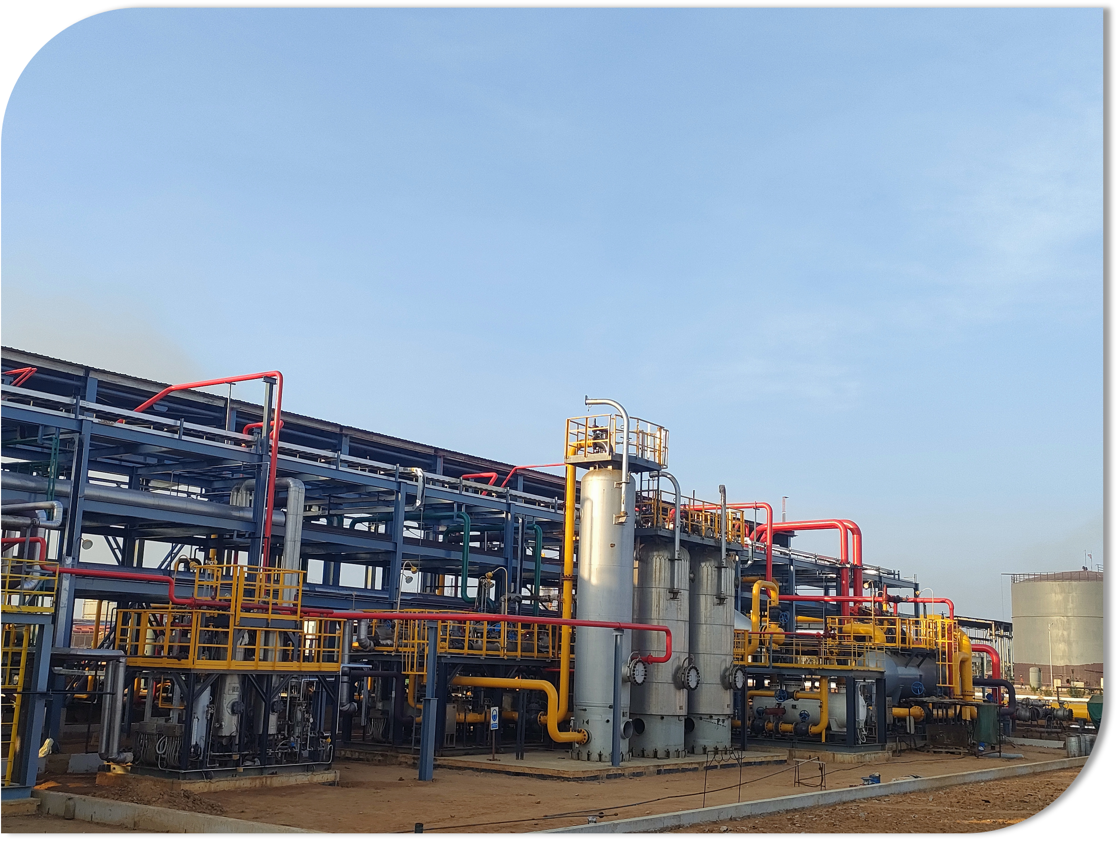
Congo (Brazzaville) Jiarou Oilfield
Associated gas recovery system included multiple gas-liquid separation stages handling fluctuating inlet conditions. Processed up to 300×10⁴ Nm³/d gas + LNG liquefaction, requiring reliable upstream separation to protect downstream equipment.
Separation equipment represents one of LINSON OIL's highest-volume product categories, delivered globally.
Warranty & Support
Our extended warranty reflects confidence in our design accuracy and fabrication quality.
From commissioning or 26 months from shipment. (Industry average is 1 year).
Process engineers available for remote consultation during start-up and slug management optimization.
Slug Flow Is a Process Reality. Let's Design Around It.
Share your inlet flow conditions -- or just tell us about your slugging problem -- and our process engineers will recommend the right buffer separator configuration. We respond with engineering, not a catalog quote.